Quantcast
Channel:
Viewing all 194 articles
Browse latest View live

Imaging Freezing Damaged Drives

$
0
0

When Atola Insight Forensic performs Imaging, it approaches bad sectors in the most gentle yet thorough way with high overall speed. But most importantly, Insight is unbeatable at imaging severely damaged drives, while providing all the necessary tools for evidence verification and proper data storage formats. Insight’s ability to succeed even with the drives that freeze in the course of imaging makes it indispensable for forensic specialists.

So why do damaged drives freeze?

When a drive receives and runs a Read sectors command, and comes across a physically or logically damaged sector, the device is unable to return a good result. Therefore it goes into Retry mode, repeatedly attempting to retrieve data from the damaged area.

However, often the drive is unable to read data from the damaged sectors and the Retry mode can last for a very long time before it decides to give up on a particular sector and return an Error.

How does Insight handle this issue?

If Insight simply waited for each Read sectors command to be completed:

  • it would take ages to get an Image of a drive with numerous errors;
  • it could cause the drive to slip into complete freeze;
  • in the worst-case scenario, further damage could be caused to the data on the drive.

For these reasons, Insight issues a Reset command whenever a drive attempts to read a block of sectors for longer than allowed by the pre-configured TimeoutReset is a device interface operation, using which Insight (the host) stops the previously sent Read sectors (or any other) ATA command so that Insight continues imaging from the next planned block on the drive.

If the device is still running Read Sectors command, even after Reset attempt, Insight will wait 3 seconds and perform another Reset command. At the moment of the second Reset, a new entry will appear in the Imaging Log reading Device hangs while reading block X – Y.

Imaging Freezing Damaged Drives

If 20 seconds after the second Reset, the drive has not been able to abandon the current block, Insight will perform Power cycle by forcibly cutting power to the drive for 5 seconds. At this point Insight will add two entries to the log:  Performing power cycle… (when the power is cut off) and Waiting for the device to become ready… (when the power is switched back on).

Should Power cycle prove successful and the drive become ready to accept the next command, there will be a final log entry for this problematic block of sectors saying: Cannot read block of data at X – Y (Timeout).

If Power cycle is ineffective, it means that the drive is still in Busy state that prevents it from becoming ready to run the next command. After that, Insight will make one or more additional power cycles.  In Insight’s default settings the Max consecutive Power Cycles option is set to five. Should all five Power cycles be unsuccessful, Imaging will be automatically terminated. It can be resumed afterwards, and Insight will continue to image all remaining sectors.

While users are able to change the default maximum numbers of Resets and Power cycles, these are set based on our decades-long experience and balance the need of data retrieving with the risk of further data loss.

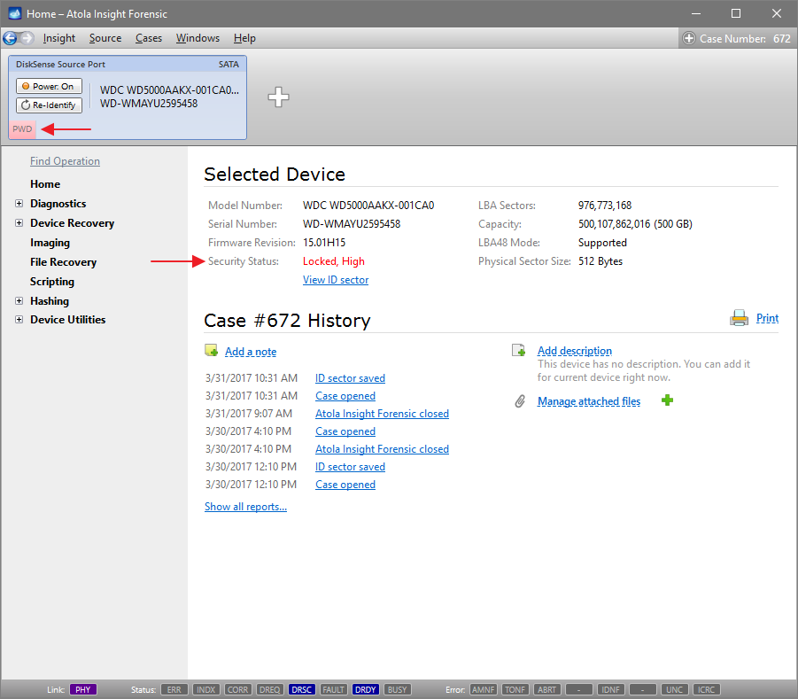
NB If prior to Imaging, you applied Change Max Address temporarily (until power cycle) option, the Power cycles performed in the course of Imaging will not affect it. The Host Protected Area will remain accessible throughout the Imaging process. Insight will temporarily remove HPA max address restriction after each Imaging-related Power cycle.

The same is true for Reset Password until power cycle option. Insight will keep the password reset throughout the Imaging process, without regard to the Power cycles applied.

The post Imaging Freezing Damaged Drives appeared first on Official Atola Technology Blog.


Screencast: Imaging Drives with Damaged Heads

Wiping multiple drives simultaneously

$
0
0

Erasing data on destination drives guarantees accuracy of the imaged data and helps verify that the drive has no errors. In the course, all sectors are overwritten with the help of selected pattern or method.

When you need to prepare multiple hard drives for imaging, Insight’s multitasking capabilities enable you to do so much faster by launching Erase/Fill on multiple drives simultaneously, including those connected to the source port.

To wipe the drive connected to the source port, remember to switch off write protection on the port so that the indicator above the switch is off and there is a notification right below the port bar saying Note: Write protection of currently attached device is OFF (see the picture below).

Then follow these steps:
1. Under Device Utilities select Fill or Erase.
2. Select Fill method among the wide range of options and click on Next button.
3. Select the range of sectors to be erased on the drive and click on Start Fill / Erase button.
4. Finally, confirm that you want to erase data on the disk in the pop-up window.

To run a concurrent Fill/ Erase process on another drive, click on the + (plus) icon in the port bar and select a drive connected to a Target port:


Then repeat the same steps to launch the process on this device:


By following the same steps you can wipe data from one source drive and three target drives, all at the same time, as shown in the picture below.

This ability to perform Fill/Erase on multiple drives makes Insight exceptionally useful for forensic units dealing with multiple cases, where evidence acquisition is an ongoing activity.

The post Wiping multiple drives simultaneously appeared first on Official Atola Technology Blog.

Screenshot Analysis: Imaging a Freezing Drive

$
0
0

Recently, we received an email from a long-standing client. The drive he was imaging contained a large number of errors. We would like to use this screenshot of a real-case imaging process to illustrate how well Atola Insight Forensic handles imaging hard drives in such dire state.

In the screenshot the numbers show that despite encountering over 1100 errors, Insight has already imaged 605 million sectors out of 1,745 million sectors it has attempted to image in this first pass. The speed may seem low, but Insight is actually able to read it, while most other imagers will likely be unable to even identify such device.

Second, in this screenshot we have yet another example of the freezing drive recovery algorithm in action, which helps make the imaging process much more efficient when imaging severely damaged drives like the one in our example. We have recently posted a guide explaining how it works and helps Insight avoid long idle periods waiting for the disk to become ready.

As for the situation in the screenshot: according to the algorithm, Insight issued two consecutive resets (only after executing the second reset Insight adds a message to the Log saying Device freezes while reading block X – Y, as shown in the red box area of the screenshot). Apparently, the drive has not become ready after both resets, and according to the freezing drive recovery algorithm, Insight executed a power cycle, which proved effective: the drive became ready to start reading the next planned block of sectors.

Finally, there are two graphs that reflect imaging progress: the upper one is called imaging map bar and shows imaging progress throughout the whole drive space. The lower one is called read speed graph and shows the time Insight spent reading recently imaged sectors. You might have noticed a few discrepancies about these graphs:

  • Why does the imaging map bar indicate that 10% of the drive have been imaged, but the progress bar looks more like 30% of the total drive space?
    The bar reflects the media space between the first and the last sectors. The percentage indicates only the ratio of successfully imaged sectors and does not include the skipped blocks: in its first pass Insight performs one-million-sector jumps when encountering bad sectors. When Insight returns to the skipped blocks during the following passes, it will allocate more time to read each sector and will add the successfully imaged sectors to that percentage.
  • Why do the red zones in the Imaging map bar look larger than those in the read speed graph?
    Each pixel in the Imaging map bar stands for thousands of sectors. The map gives priority to showing the location of errors as opposed to showing the location of good sectors. And being limited by the screen size and resolution, the imaging map bar may look very red in the course of imaging a drive with a large amount of errors. Especially during the first pass, before attempting to read the problematic sectors more thoroughly.
  • Why do the equally sized ranges in the read speed graph, contain substantially different numbers of sectors, according to the LBA values? 
    range 1. there are 819,200 sectors between 1,733,217,921 and 1,734,037,121,
    range 2. there are 4,802,816 sectors between 1,734,037,121 and 1,738,839,937,
    range 3. there are 6,794,624 sectors between 1,738,839,937 and 1,745,634,561.
    The spans are different because of the number of bad blocks of sectors located between them. During the first pass, Insight performs a jump by 1 million sectors each time it encounters a block of sectors, which it cannot read.

The post Screenshot Analysis: Imaging a Freezing Drive appeared first on Official Atola Technology Blog.

Imaging a Source Drive to an E01 File with a Double Hash

$
0
0

In recent years, E01 file format has become the de facto standard format for forensic purposes due to its ability to store not only a physical or logical copy of a source drive, but also case and evidence details. E01 file can also contain both MD5 and SHA-1 hashes. And it is considered a good practice among forensic specialists to calculate both hashes while imaging the evidence so that they are included in the E01 file.

To image a source evidence drive to an E01 file you have to add a new target file.

Selecting a new E01 file

1. In Imaging category of the left-side menu you can click on Create New Session link and in the Target Device Selection window click on Add Image File link.

2. In the Image File Selection window select E01 file extension in the drop-down menu to create an image file with this extension and type the name you prefer in the File Name field.

3. Fill out all the relevant fields in the Image File Options window (you can also do it later in the Home page of the file when it is created):

4. Click on Select button in the Target Device Selection window.

As a result you get is an E01 file with current 0 bytes capacity created (its final capacity will be defined by the amount of imaged data it contains plus the metadata).

Imaging & calculating the hashes

  1. Go to Imaging category of the left-side menu and click on Create New Session link
  2. In Preset line click on the Show settings link
  3. In Passes and Hash tab check the Hash source during imaging box
  4. In Hash method drop-down menu select Linear
  5. In Hash type drop-down menu select MD5 and SHA-1
  6. Click on Start imaging button

Upon completion of imaging, you will see both MD5 and SHA-1 hashes indicated in Imaging Results page:

The post Imaging a Source Drive to an E01 File with a Double Hash appeared first on Official Atola Technology Blog.

Calculating Hash During Imaging

$
0
0

Atola Insight Forensic supports hash calculation of both source and target devices in conjunction with imaging. We have developed highly flexible functionality to help optimize evidence acquisition process to fit one’s internal procedures as well as avoid causing further damage to fragile media.

To view the hashing options:

  1. Go to Imaging category of the left-side menu and click on Create New Session link
  2. Select the target device or file
  3. In Preset line click on the Show settings link
  4. In the upper part of the Passes and Hash tab there are three checkboxes:
  • Pre-hash source device
  • Hash source during imaging
  • Post-hash target device(s)

Multiselect is available, which allows an operator to use all three of these options.

However, Pre-hash source drive option must be used with caution: although pre-hashing can be required by an investigator’s internal procedures, when dealing with drives that have been diagnosed with hardware failure, this operation may cause further damage to the drive before essential data is imaged.

On the contrary, Hash source during imaging is the most appropriate way to calculate the hash of a fragile source evidence drive. In this case, Insight only needs to read the data on the drive once to both image and calculate the hash, thus minimally using the drive’s hardware.

NB Linear hash can only be calculated by reading data in sectors consecutively in one pass. Therefore ticking Hash source during imaging checkbox and selecting Linear or combined Linear and Segmented option in Hashing method drop-down menu leads the number of passes to be limited to one. When dealing with a damaged drive, we strongly recommend using Segmented hashing, as this method supports multi-pass imaging and handling of bad sectors and provides better resiliency against data corruption. For more details please follow this link: Segmented hashing.

Post-hash target device(s) option allows to properly record the calculated hash in the case. Since this operation does not require reading the source drive, it is safe to use this option while imaging either good or damaged drives.

The post Calculating Hash During Imaging appeared first on Official Atola Technology Blog.

Lifting HPA and DCO restrictions

$
0
0

Both HPA (host protected area) and DCO (device configuration overlay) features were created by hard drive manufacturers as hidden areas reserved for storing vendor utilities or simply to make a drive appear to have a certain number of sectors (smaller than the actual drive capacity). But it is many years ago that end users learned to modify and write to these areas of hard drives with the help of open source and freely available tools. For digital forensics specialists, it means that without the ability to identify such hidden areas of a drive and image the full physical image including data in these areas, the evidence they get may be incomplete and lead to inaccurate investigative conclusions.

When you connect a hard drive to the DiskSense unit, in addition to the standard Identify device command, Atola Insight Forensic automatically sends two commands to look up the drive size as set in drive’s firmware: Read native max address and Device configuration identify. If drive size has been limited by DCO or HPA, Insight will draw attention to these changes by adding corresponding red indicators to the DiskSense Source Port.

To get more details about the modifications that have been made to the drive’s firmware, run Automatic Checkup and see the Firmware section of the Diagnostics report.

There you will see three lines indicating the drive’s Max Address according to different records in the drive’s firmware:

  1. The Max Address according to device ID line shows the max address from the ID sector, affected by both HPA and DCO restrictions if those are applied.
  2. Native Max Address indicates max address ignoring HPA limitation that may have been enabled, yet affected by DCO restriction.
  3. Max Address from DCO is the line that gives you the actual drive size.

A Diagnostics report of a drive that does not have HPA or DCO activated will have the same value in all three lines.

To disable any limitations that have been applied to the drive’s firmware, click on the Unclip HPA/DCO subcategory under Device Utilities category of the left-side menu and click on Unclip button.

Please note that Write Protection switch needs to be disabled on the DiskSense unit to perform this operation, as Unclip HPA/DCO implies making changes to the drive’s firmware, and Write Protection won’t let perform such changes.

Atola Insight Forensic lifts HPA and DCO restrictions in a matter of seconds and enables access to all data on the drive.

Lift HPA until power cycle

Often, due to internal procedures, forensic specialists are not allowed to make any changes to the drive, therefore they cannot disable HPA and DCO restrictions and access data in the hidden areas. But with Atola Insight Forensic it is possible to lift HPA limitation until the next power cycle, which helps avoid permanent changes to the drive.

To use this feature, go to Host Protected Area subcategory of the Device Utilities category of the menu and click Read HPA parameters link. By clicking Set as current link you will automatically change Current Max Address value to that of Native Max Address. Then tick the Change Max Address temporarily (until power cycle) checkbox and click Change Max Address button.

This will allow access to the data in the area previously protected by HPA, yet as soon as you power off or detach the drive, the HPA will be in place again.

NB If the drive contains damaged areas and Insight needs to perform power cycles during imaging, such power cycles will not affect the temporarily disabled HPA: Insight will temporarily remove HPA max address restriction after each imaging-related power cycle, and HPA will remain accessible throughout the imaging process.

For more information about imaging of freezing drives, please follow this link.

The post Lifting HPA and DCO restrictions appeared first on Official Atola Technology Blog.

Extracting and Resetting an Unknown ATA Password

$
0
0

Insight can recover and/or remove unknown HDD passwords (also known as ATA passwords) and for most hard drives the unlocking process is fully automated.

When a device is connected and identified as locked with an ATA password, there is a corresponding PWD indicator displayed in the port, and Security Status in the Home page says Locked, High or Locked, Maximum. High and maximum are password protection levels that the operator who locked the device selected. Although information about it may be relevant to the investigator, both security levels are supported by Insight’s password recovery functionality, therefore this information is not important for the purpose of this guide.


To perform a complete Diagnostics, Insight needs to have a hard drive unlocked. Therefore we suggest that when dealing with a locked device, password recovery is performed before running the Automatic Checkup.

Password Extraction, Reset and Reset until power cycle

Under Device Recovery category of the left-side menu select Password Recovery subcategory. There are 3 options of dealing with a locked hard drive:

  • To display the password without unlocking the device at this moment, click Extract button. This option does not require write protection on the source port to be switched off.
  • To work with the data on the drive without permanently resetting the password, tick Reset Password until power cycle checkbox and then click on Reset button. This way write protection stays enabled on the source port, and no changes can be made to the drive.

NB. If Reset Password until power cycle option is selected, no power cycles that are executed in the course of automatic checkup, imaging or other operations will affect the temporary unlocked status of the device. Only a deliberate power cycle, such as clicking on Power button, will change the Security status of the drive back to Locked.

  • Finally, to permanently unlock the device, switch off write protection and then click on Reset button.

For the list of hard drives currently supported by Insight’s automatic password recovery, please follow this link.

Please note that this guide is applicable to all supported Samsung, Toshiba and Western Digital hard drives. To unlock a Seagate drive, please connect the device to the Serial port of the DiskSense unit and then follow the same steps. Hitachi drives require the use of the password extraction adapter: for more information please follow this link.

The post Extracting and Resetting an Unknown ATA Password appeared first on Official Atola Technology Blog.


Verifying Damaged Target Images with Segmented Hashing

$
0
0

Last November Atola Technology team presented a new hashing method called Segmented hashing. Unlike the conventional linear hashing, segmented hashing produces not a single hash, but a list of hashes of corresponding LBA ranges of the image saved into a CSV file in this format:

Hash, start LBA, end LBA

By validating all hashes on the list, you can prove that the entire image has not been modified. For more information about this hashing method, please follow this link: Segmented Hashing.

While this method of hashing has a number of benefits for forensic specialists, among its strongest advantages is its applicability to damaged drives.

For one, this non-linear hashing method allows calculating hashes of the good areas of evidence media, while bad areas that are impossible to read and image, are left out of the calculation.

Secondly, if your acquired evidence image is damaged at some point in the future, with the regular linear hashes you will get a hash mismatch upon verification, and the entire image becomes useless, whereas with segmented hashes only the hash of the damaged segment will become invalid. For example, in the case of a 4TB hard drive, if the default 4GB segment size is applied, one invalid hash will account for only 0.1% of the drive, while the remaining 99.9% of hashes can still be verified.

Verifying segmented hashes

For instance, you have imaged a source drive and calculated its segmented hashes, the CSV file is stored on your computer. Now let’s simulate a change of the evidence image to see how Segmented hashing helps us identify the areas, whose integrity has not been compromised.

Step 1. Select the target image in the top Port bar. In the Disk Editor subcategory of Device Utilities category of the left-side menu, we can open any sector of the drive. There we can change one byte in sector #35,000,000.

Change one byte in Disk Editor


Step 2. In the Hashing category of the left-side menu there is Verifying Segmented Hashes subcategory. This is an automated way to verify the segmented hashes in an existing CSV file against the target image. Select the file with segmented hashes calculated during imaging and click Start.

Start segmented hash verification


Step 3. Hash verification is in progress. Here we see 18 segmented hashes checked. Hash for the interval that includes sector 35,000,000 is invalid.

Segmented hash verification in progress


Step 4. Hash verification finishes with the proper case report automatically created, also in CSV format.

Segmented hash verification report

This is how segmented hashing helps you avoid the whole image being compromised when a small area of the evidence target is damaged.

The post Verifying Damaged Target Images with Segmented Hashing appeared first on Official Atola Technology Blog.

Q&A during Forensic Europe Expo

$
0
0

Atola team attended the annual Forensic Europe Expo on May 3 – 4 in London. We were pleased to meet both our existing and potential customers, and answer their questions about Atola Insight Forensic. Those of you who were not able to attend this event may have similar questions, so here are the most frequently asked ones at the Expo and our answers to them. We would be happy to answer any further queries you may have, so please don’t hesitate to write a comment below or send us a message here.


Question: Does write protection work for SATA source drives only?

Answer: No, write protection works for all source ports: SATA, IDE, USB & extensions.


Question: You claim that Atola Insight Forensic is capable of imaging even bad drives. What does a bad drive mean?

Answer: By bad drives we imply various types of drive issues, namely:

  • Scratches on the media surface
  • Magnetic layer wear-out
  • Degraded or even non-working head
  • Drive freeze after reading attempt
  • Firmware issues
  • Bad sectors

Atola Insight Forensic is capable of dealing with devices, which competitor products cannot even identify.


Question: What are the advantages of Atola Insight Forensic compared to ddrescue open source data recovery tool?

Answer: Here are some of the functions that Atola Insight Forensic provides and that ddrescue lacks:

  1. For Insight we have developed functionality that specifically helps image freezing damaged drives.
  2. Insight’s diagnostics function identifies damaged heads, while advanced imaging settings allow head selection to perform imaging in a fast and, most importantly, cautious manner to avoid causing further damage to the evidence drive.
  3. Insight can image to multiple targets at the same time, both hard drives and files.
  4. Forensic procedures require hash calculation to be a part of the acquisition process. Insight has a very flexible hash calculation functionality: it can simultaneously calculate MD5 and SHA hashes of the source before, during or after imaging, and target drive’s hash can be calculated in conjunction with imaging or as a separate action.
  5. Built-in write protection.
  6. Insight’s in-depth diagnostics helps identify the drive status and, based on that, the right way to handle the drive for successful data acquisition.
  7. Insight’s overcurrent protection detects when the hard drive draws abnormal current and stops the hard drive to prevent any further damage to the system and the drive.
  8. Insight’s automatic password removal function can extract an unknown ATA password and unlock the drive in under 2 minutes with just a few mouse clicks.

These are just a few of the key features that Insight has to offer as opposed to ddrescue. For more information about the product please follow this link.


Question: When coming across bad sectors on the source drive in the course of imaging, how does Insight deal with the corresponding sectors on the target drive?

Answer: Such sectors can be either left alone (skipped), or filled with a pattern. The default pattern that is used to fill the sectors that are not readable is 00. However, it is possible to enter any other pattern or even load the pattern (of any length) from a file. To use this option:

  1. Navigate to Imaging category of the left-side menu
  2. Click the Create New Session link
  3. In the Preset line click the Show settings link
  4. Tick the check box next to Fill unreadable sectors with the following pattern (HEX):
  5. Leave the default pattern as it is or enter/upload a new one
  6. Click Save settings button if you would like to make this new pattern the default one or, should it not be the case, simply click Start imaging button.

The post Q&A during Forensic Europe Expo appeared first on Official Atola Technology Blog.

Case Management: Finding and Opening a Case

$
0
0

Insight’s Case Management system records every step of data acquisition process saving them into reports grouped by cases.

To view the whole list of cases and their devices:

  1. Go to Case category in the top menu
  2. Click on Search/Open option

In the Search and Open Case window you will see the list of all the devices that have ever been connected and identified by your Insight.

It is possible to search for cases using multiple criteria and sort the results ascending or descending in any of the columns.

Please note that it is possible to store multiple devices under the same case number, allowing you to keep track of all devices related to a certain case.

Once a device is selected, you get a preview of the case including device details: when the case was created (i.e. the device was connected to the unit and identified by Insight for the first time), last time it was opened, the device model, serial number and description.

The case opens as a separate port in the Top Bar of the Insight window.

The post Case Management: Finding and Opening a Case appeared first on Official Atola Technology Blog.

Creating a logical image of a source drive

$
0
0

While physical imaging involves sector-for-sector copying the whole evidence drive from the first LBA to the last one, logical acquisition implies bit-for-bit copying of the file structure.

Logical acquisition is handy, when time is limited and you need to quickly start working with the file structure. At the same time, logical image does not include remaining fragments of previously deleted files, which makes this imaging method incomplete. On top of that, hash values of the source and the target will not be identical. Therefore, for profound investigation, it is still preferable to use a physical image.

This guide will show how Atola Insight Forensic’s flexible imaging functionality enables users to perform selective logical imaging.

In the Imaging category of the left-side menu there is I want to image drop-down menu, where you can select All sectors with data or All sectors with metadata options.

When you choose All sectors with data, you can image the whole system structure of the drive including folders and files, while omitting the areas with no data or fragments of previously deleted files.

By going for All sectors with metadata option you can image the system structure without data within its files (e.g. MFT in NTFS) for file browsing and selecting specific files to be imaged in full. For more information on this please watch this video guide: Benefits of Imaging Metadata.

When you select either of these two options, imaging log adds a message about the partitions Insight has been able to find.

Once imaging is complete, you can view the structure of the logical image you have obtained by clicking Analyze target image.

This will open the Target port.

  1. Click Scan partitions button
  2. Select any of the imaged partitions you want to
  3. Click Open partition button

In our example, we have imaged all sectors with data, and the partition we open contains the file structure and files, which we can explore, open and analyze.

The post Creating a logical image of a source drive appeared first on Official Atola Technology Blog.

Calculating MD5 and SHA1 hashes of an existing E01 file

$
0
0

It is not uncommon that source evidence drives and their images may be involved in a long-running investigation case or wait to be presented in court for months or even years. Data stored on hard drives or image files may get corrupt over time. That is why an investigator may need to ensure the integrity of data on these devices or image files before resuming to work with them or presenting them in court.
Over the years, E01 file format has become a popular format for forensic purposes due to its ability to store not only the physical or logical copy of the source drive, but also case and evidence details. E01 file can also contain both MD5 and SHA-1 hashes. And it is considered a good practice among forensic specialists to calculate both hashes while imaging the evidence so that they are included in the E01 file.
To view the hash calculated for an E01 file with Atola Insight Forensic, open the file by pressing the Plus icon in the port bar and then selecting E01 image files (*.E01) file extension in the drop-down menu to view existing files with this extension.

In the Home page look through the File History and click on the Imaging target link.

This will open an Imaging target report, at the bottom of which you will be able to see both hashes calculated during the imaging session.

You may leave this window open or save the report as a pdf file to compare the hash with the newly calculated one later.

Then go to Calculate Hash page in Hashing category of the left-side menu and select Linear in Hash method drop-down menu and MD5 and SHA-1 in Hash type drop-down menu.

Once the hashes have been calculated, you can make sure that the two sets of hashes are identical.

The post Calculating MD5 and SHA1 hashes of an existing E01 file appeared first on Official Atola Technology Blog.

How we test our devices

$
0
0

Today we are offering you a sneak peek into Atola Technology office to show you our device storage system.

As you know, Atola Insight Forensic and Atola Recycler both support the vast majority of 1.8-inch, 2.5-inch, 3.5-inch IDE, SATA and USB hard drives, USB Flash media as well as SD, Compactflash, and Memory Stick cards. Over the years, we have accumulated hundreds of devices to develop and test our systems on them. Some of the drives date back to 2003, when the company was founded, others were purchased or donated more recently.

Many are damaged, yet they are precious to us: we actually bought most of them in this condition to make sure our acquisition systems are equal to the challenge of imaging such devices.

Each device has a unique history with us, so from the early days, we have had a database listing the drives and documenting their specifications, origin, condition and contents. Airtable allows adding various details including pictures of actual devices to help us quickly find the most appropriate drive for our purposes.

But the fact that the drives were stored in boxes sorted by a few rough criteria made finding devices a challenging task. At one point we realized we needed to have an efficient storage system in place, which would help us store the drives correctly and locate them efficiently. And no generic solution would suit us. So we hired a company to design and produce it for us. That is how this beauty came into existence:

Each drive has a number, is stored in a static-shielding bag tagged with colored stickers to help immediately identify the condition of a drive if you need to grab an appropriate drive quickly without checking the database. Our team members each have a set of tokens with their names that must be left in place of the drives when they are removed from their cells. All for easy tracking of the drives and their whereabouts.

The post How we test our devices appeared first on Official Atola Technology Blog.

Case Management: Print reports from a case

$
0
0

Insight’s Case Management system includes flexible printing functionality. To print a report click the Print link in the case’s Home page.

In the Print Case History window you get all the reports listed, sortable by date or by reported operation. It is possible to tick just some of the reports or select all reports in the case by ticking the check box in the header of the list. Below there are all pictures attached to the case, which you can also select to be printed.

At the top of the Print Case History window there are four check boxes with report listing and printing settings (click on the Case Management arrow to view all check boxes):

  • Insert page break after every report on print
  • Also show miscellaneous reports hides/displays all reports of seemingly minor importance, yet essential to some forensic specialists in accordance with their internal procedures
  • Also print CSV logs allows the printed version of the reports to include operation logs saved in CSV format
  • Also print segmented hashes also enables segmented hash saved in CSV files to be included in the printed version of the reports

It is possible to print or save the selected reports and pictures in a PDF, HTML or RTF file by clicking Save to file… or Print buttons.

If you have ticked the two later options, this is how the log and the segmented hashes will be displayed in the report:

The post Case Management: Print reports from a case appeared first on Official Atola Technology Blog.


Comparing Hashes of Source and Target to Find Modified Data

$
0
0

So you have a Source evidence drive and its image on a different device, and you have a record that their hash values were identical in the past.

If you get a different hash value when you calculate the hash of the target now, it could be due to hardware failure, or because the device containing your image was used by a third party.

To understand how substantial these changes are, you will want to locate the sectors that have been modified.

  1. In the Disk Utilities category click Compare subcategory.
  2. Make sure that the whole range of sectors of the drive and radio button next to Device on DiskSense Target Port option is selected
  3. Click Compare button.

Atola Insight Forensic’s high-performance compare function will compare the source and the target and will help you identify and locate the modified sectors:

The post Comparing Hashes of Source and Target to Find Modified Data appeared first on Official Atola Technology Blog.

Atola Insight Forensic 4.9 – Thunderbolt extension

$
0
0

We are delighted to announce the release of Atola Insight Forensic 4.9!

With this release we introduce our new Thunderbolt extension module, which will enable forensically sound imaging and other operations on all generations of MacBooks.

The full list of Atola Insight Forensic 4.9 changes can be found here: Atola Insight Forensic Changelog.

Supported interfaces and functionality

Thunderbolt extension enables Insight to work on all MacBooks with the following interfaces:

  • FireWire
  • Thunderbolt 2
  • Thunderbolt 3

With the help of Thunderbolt extension module you can perform such operations:

  • imaging
  • hash calculation
  • hash verification
  • comparing
  • media scan
  • file recovery

2016 and 2017 generations of MacBooks have non-extractable SSD drives, so the only way to handle such drives is by booting the MacBook in Target mode. In fact, with Insight’s Thunderbolt extension you can operate on all Macbooks the same way, hard drive extraction is no longer necessary.

If you want to learn more about other 4.9 changes, visit this page: Atola Insight Forensic Changelog.

Where to buy

If you still do not have an Atola Insight Forensic and would like to place an order, this can be done directly via Atola Technology, or from a distributor near you:

http://atola.com/wheretobuy/

Please contact our Atola Technology sales to receive more specific information:

P.S. Dear customers, we appreciate your feedback and will take it into account when making changes to the product. Therefore, please feel free to write your thoughts or ideas as comments below.

The post Atola Insight Forensic 4.9 – Thunderbolt extension appeared first on Official Atola Technology Blog.

Connecting MacBook using Thunderbolt extension module

$
0
0

Last week we released Atola Insight Forensic 4.9, which includes Thunderbolt extension module. This extension provides Insight users with the capability to image, calculate hash and perform other forensically sound operations on all generations of MacBooks.

This guide will explain how to connect a MacBook to Insight using Thunderbolt extension.

Extension and cables

Thunderbolt extension enables Insight to operate on all MacBooks with FireWire, Thunderbolt 2 and Thunderbolt 3 interfaces. There is no need to remove the SSD, Thunderbolt extension allows connecting the whole Apple laptop to Insight.

The extension module comes with:

  • Thunderbolt 3 to Thunderbolt 2 adapter (by Apple)
  • Thunderbolt 2 to FireWire adapter (by Apple)
  • FireWire cable

Connecting MacBook to DiskSense unit

1. Connect MacBook to DiskSense unit with the help of Thunderbolt extension and the FireWire cable (NB Both MacBook and DiskSense have to be turned off). Use the adapters to connect to the MacBooks with Thunderbolt 2 or Thunderbolt 3 interface.

2. Boot the MacBook in Target Disk Mode. To do that, start it up while holding down the T key. You should see a Firewire or Thunderbolt icon displayed on screen signifying that Target Disk Mode is detected and working.

3. Start DiskSense unit and launch Atola Insight Forensic on your computer.

4. Select Identify device option in the pop-up window.

5. In Source – Select MacBook Case window click Add new case button.

6. If this is the first time this MacBook is identified by Insight, you need to enter the Serial number of the MacBook in the pop-up window and click OK. The device has been identified. (NB MacBook’s serial number can be found on the bottom case).


Now you can perform these operations with the connected MacBook:

  • imaging
  • hash calculation
  • hash verification
  • comparing
  • media scan
  • file recovery

When a MacBook is connected to Insight for a subsequent session, it is possible to simply select the appropriate case from the table.


The post Connecting MacBook using Thunderbolt extension module appeared first on Official Atola Technology Blog.

Case Management: Changing Details in a Case

$
0
0

Insight’s case management system has been created to help users efficiently keep track of hard drive-related information.

Even if a hard drive has already been used for a while, imaging and hashing have already been performed, it is still possible to open the case and make adjustments to its details.

Click the Plus icon next to the Case Number in the top right corner.

Now you can enter or change the Case Number and Description. To save your changes click OK button.

You will see the description visible next to the Case History. For quick changes, you can also click Change link located right below the description.

A little lower there is a green Plus icon, which you can click to add a document or an image to the case.

In the Attach File window enter the file location path and leave a comment in the corresponding field.

If you tick the Copy to work folder check box, the file will be copied to the same folder where any other related files are located, e.g. tables with segmented hashes, logs, imaging maps, file signature lists etc.

You can now see all the uploaded files in the case’s Homepage below the description, and you can view all the details and change them when necessary by clicking Manage attached files link.

Attached Files window contains the list of files including an icon representing the file type, the name, the folder where the file is located, the date when the file was attached to the case and the comment added by the user.

Right-clicking a file provides the Edit option enabling a user to edit the Comment or copy the file to the case folder at any time.

The post Case Management: Changing Details in a Case appeared first on Official Atola Technology Blog.

Multi-pass imaging of damaged drives

$
0
0

Atola Insight Forensic has a complex imaging functionality, which allows imaging even physically damaged hard drives, while avoiding further drive deterioration. Damaged drives require a complex imaging approach, which would balance thorough data extraction with forensics’ need in expediency and measured treatment of damaged media.

Most imagers have a linear imaging process, and whenever such imager encounters a bad sector on a drive, the process slows down drastically, which often causes the drive to freeze. To speed up imaging of damaged drives and maximize the amount of successfully retrieved data, Insight operates using a special imaging algorithm that provides deliberate timeout and block size control.

Using small block size pays off when you need to thoroughly retrieve maximum data from an unstable drive, but it also significantly slows down imaging process. What’s worse, such approach increases the possibility of causing further damage to the media. That’s why Insight’s multi-pass imaging engine uses large blocks with short timeouts on the first few passes, scheduling reads inside slow areas for later and then using the smallest block size on the last pass when fewer sectors are left to be read.

This technique helps achieve imaging speeds of 500 MB/sec in good areas of the drive, while approaching bad areas in the most gentle way possible and reaching unbeatable overall speed of disk duplication.

The best part is that Atola Insight Forensic will handle block sizes automatically, thus providing the best possible results in the shortest amount of time. This allows Atola Insight Forensic to be faster in virtually any job than any other data recovery or image acquisition tools commercially available.

Block sizes and timeouts are adjustable. However, the default settings of the passes are based on our decades-long experience in data recovery market to fit most problematic drives. Therefore, it is advisable to follow them, unless a particular drive requires specific settings.

On the first pass, Insight allows 1-second Timeout per block, and the Max read block size is set to 4096 sectors. The settings of the first pass allow smooth sequential imaging of all modern hard drives, whose media is sound. But when imaging damaged drives, these settings make Insight skip any areas that slow down reading and perform Jump on error by 1,000,000 sectors at a time. These settings ensure imaging data from the healthy areas of the drive at top speed, while forcing Insight to return to the problematic areas during the following passes, splitting such areas into smaller ones and allowing more time for reading the data within.

While Max read block size remains the same during the second and the third passes, the Jump on error is set to 20000 sectors and 4096 sectors respectively and slightly longer, 5-second Timeouts are allowed for attempted reading of the blocks.

On the fourth pass, both Jump on error and Max read block size are yet again reduced, this time to 256 sectors.

On the fifth pass Insight allocates 60-second Timeouts to read the Maximum block size of 256 with just 1-sector Jump on error. It is the last and the most scrupulous attempt to read the remaining bad areas of the drive.

After the final pass the Imaging Results report will appear to show the eventual number of errors on the drive and other detailed statistics.

When looking at the settings of the imaging passes, you will see the Reverse direction check boxes. With this function selected, Insight will approach skipped areas of the drive from the other side on any selected pass. This way Insight can get more data from a drive before entering a damaged zone, which needs to be concentrated on during the following passes.

Another option in the imaging pass settings, which is worth mentioning is Disable read look-ahead option. Most contemporary hard drives have read look-ahead functionality, which makes the drive read more blocks sequentially than requested by software. In good drives, this functionality helps the drive to operate faster by reading more data and caching them. But with bad drives, read look-ahead leads to bad areas being addressed more often, which slows down the process and may lead to a complete freeze of the drive. In such cases, disabling read look-ahead option is advisable.

Please note that when dealing with a damaged drive, we strongly recommend using Segmented hashing because this method supports multi-pass imaging and handling of bad sectors, and provides better resiliency against data corruption.

To read about the way Insight handles imaging of freezing damaged drives please follow this link.

The post Multi-pass imaging of damaged drives appeared first on Official Atola Technology Blog.

Viewing all 194 articles
Browse latest View live